The bench
The pool is what hotbits serves; this is the bench it comes from. A Geiger tube counts in a steel case on its own supply, an optocoupler carries each count across as light, and an ESP32-C6 outside the case times every edge in hardware before the server turns the gaps between them into bits. The bring-up was done the way the NES bench was: a scope driven from a script, the board flashed from the bench, and every step written down.
These are revision F of the drawings. Nothing on the sheets is marked not confirmed any more: the counter is alone on the chassis supply, the emitter is on its own brick outside the box, and the detector and the optocoupler are sealed in a container inside the chassis. The one thing still unread is whether the chassis is bonded to a ground.
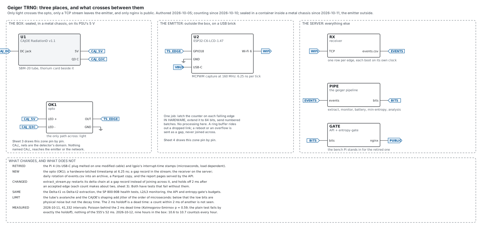
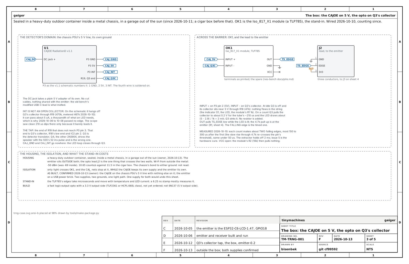
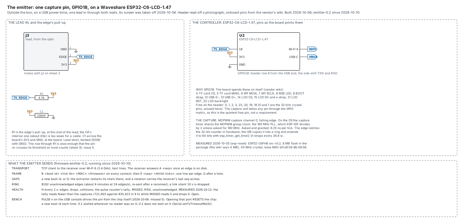
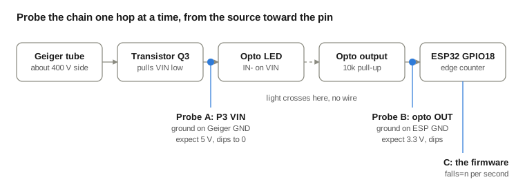
The whole package, every sheet framed and numbered: Geiger TRNG emitter: the detector and an ESP32-C6 in a box: drawing package TM-TRNG-001 rev F (PDF)
What the instrument is
How a decay becomes a byte: the counter, the bits, the tests that refuse to serve, and the gateway in front.
- The instrument: A Geiger counter whose every count is timed in hardware, and the chain from a decay event to a byte somebody can fetch.
- The bits: One bit per pair of gaps, with the bias cancelled by symmetry rather than by correction.
- The health tests: Three layers on three timescales, and the one that refuses to serve.
- The gateway: Why the open endpoints closed, what stayed open, and what a browser is allowed to see.
Building the bench
The emitter as drawn and as built: the drawings, the boards, the parts, and which ESP32 does which job.
- Which ESP32 does which job in the NES notebook: Which Espressif chips can be a Bluetooth keyboard, which a USB one and which both, read from the vendor's own headers for eight of them rather than remembered; the comparison that moved the pad onto a P4 module.
Experiments at the bench
The scope on the signal chain, what the counter's own timing costs in counts, and how the source's quality is tracked.
- Using an oscilloscope, for software developers in the NES notebook: A scope as a debugger for the wire, taught on a real fault: a Geiger counter that clicked while its firmware counted nothing. The ground clip, the trigger as a breakpoint, bisecting a signal chain, scripting the scope over SCPI, and the ways the instrument itself was wrong.