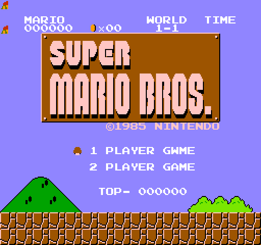
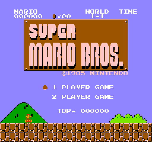
Point at the cyan letters, then the brown sign, with the model on one side and a real console on the other.
What the engineers measured on these pictures
ComparedFlat blocks, mean differenceHue, middle valueBrightness pattern alike
model against decoder0.67 of 25512.6 degrees0.95
model against grabber1.26 of 25514.1 degrees0.95
The flat blocks agree, because most of a title screen is black. The hue does not. The logo's brown is (148, 92, 0) in the model, (132, 73, 0) off the scope and (121, 69, 0) off the grabber; the lettering's cyan is (59, 200, 251) in the model against (45, 200, 205) and (67, 202, 202). Where the two eyes, two different decoders on the one signal, agree to a degree, the model sits twelve to fourteen degrees away on the same colours: bluer in the cyan, warmer in the brown.
The part's output under load. Folding the real waves by subcarrier phase shows what the model's square waves are not: on the part, the rise takes about six phases and the fall about three, the low level sits a tenth of a volt under the table's, and the cyan's plateau at 1.05 V is rounded where the brown's at 0.80 V is not. That is the 2C02's known differential phase distortion (nesdev, "NTSC video"): the PPU's output impedance depends on the level, the board's capacitance slows the higher edges, and the effective hue rotates with the voltage, brighter colours more. The wiki models it as an RC lowpass whose time constant follows the voltage; applied to the model's waves it rotates row 2 by 14.7 degrees at its amount 4 (the cyan's 14.4), but row 1 by 7.5 where the brown measured 1.8, and it rotates every hue of a row alike, as the measurements do. What the title1 session had that the earlier records did not is the grabber on the same output as the probe: a different load on the part's output stage, a stronger and more nonlinear slew than one constant fits.