The bench
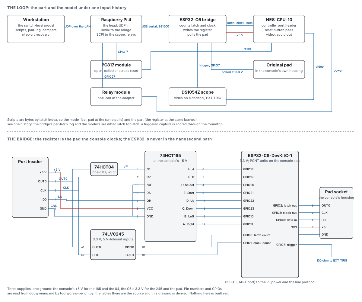
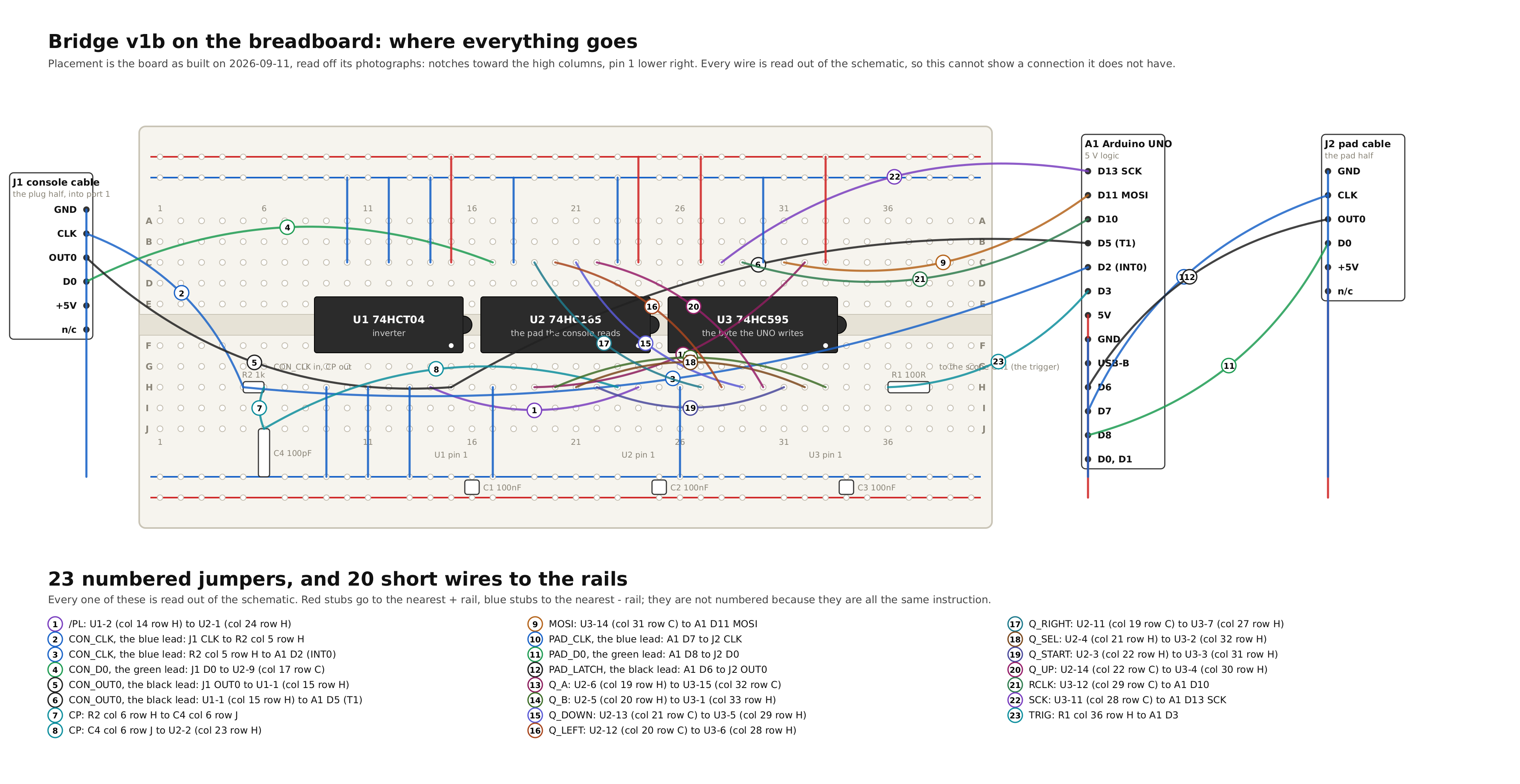
Every milestone the machine could reach on its own is done, so what the model still does not know about the real console waits on a bench, and the bench is what we are building next. A bridge sits between the console’s controller port and an original pad. A shift register on the bridge is the pad the console reads; a microcontroller writes its buttons between polls and counts the console’s latch and clock pulses in hardware; and a Raspberry Pi on the network takes scripts, drives the reset and power relays and triggers the scope. A script is a list of button bytes by poll number, so the model and the real console see exactly the same presses. The bridge logs every poll, the model logs every poll, and we compare the two logs poll by poll; a triggered capture is scored the same way the picture milestone scored its roundtrip. The plan names four milestones and their checks before any firmware, and the first, listening in on the controller port, has already changed the model. We asked what a DMC fetch does to a pad read, the switch-level 2A03 answered before the real part could, and the core, the fast chip and the console all changed for it, each change guarded by a test that goes red without it. Every milestone’s tool now exists ahead of its hardware, from the head that plays a script onto the bridge, the relays and the scope, to the search that finds the first poll where the real console and the model disagree. Each was tried against a stand-in, with a sabotaged run that has to go red. The drawing below is generated from the wiring tables by a script, so it cannot disagree with them. The plan, the wiring, the script and the running report are in the notebook; the repository is github.com/tinymachines/nes-bench.
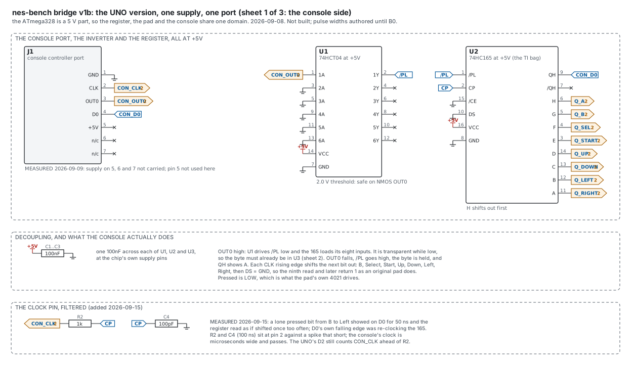
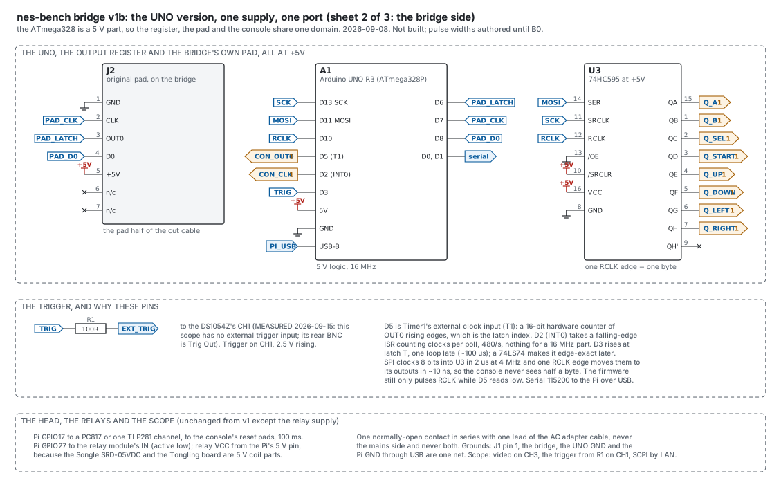
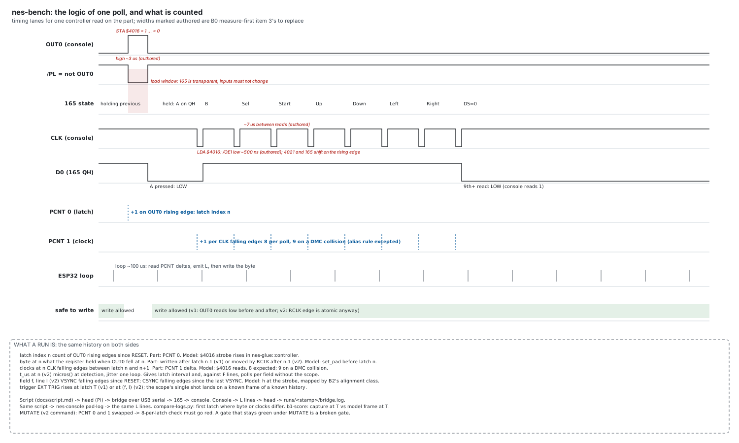
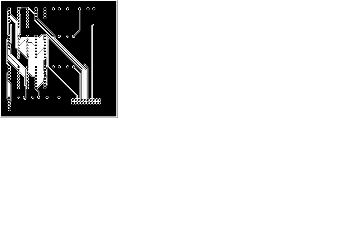
The parts are on the desk and the wiring is next, so the build is written out as five sittings, one command each, and what comes back is a lab notebook. It is the build as it actually happens: fourteen steps, each ending in a measurement rather than an opinion, every attempt kept including the ones that failed, and a photograph at each stop. Two of the steps replace numbers this site currently marks as estimates: the scope on a pad’s own port measures the latch and clock pulses the timing figure above only guesses at, and the joined bridge answers whether every poll really carries eight clocks. The notebook is generated from the tool that walks the build, so nothing in it is typed, and the site refuses to publish one its own log does not support. The same build is also a printable drawing package: framed landscape letter sheets, each with a title block, a sheet number and its own revision strip, with the two drawings that will not print legibly at that size asking for bigger paper rather than being shrunk onto it. It carries the schematic, a breadboard layout that says which hole every part and every jumper goes in, the parts list and the wiring list. Only the placement on that layout is a choice; every wire on it is read back out of the schematic, so the picture cannot show a connection the drawing does not have. The two-port bridge, the one that wants a board rather than a breadboard, has a package of its own: four schematic sheets, because eleven parts and forty-two nets do not fit on one page anybody can print. That board is routed, two layers with ground poured on the back and supply on the front, and the routing is a recorded file the build applies rather than a step anybody has to repeat. Whether every net is joined and whether any copper sits too near copper of another net are asked of the finished board, not taken from the router’s own report, because the first time we ran it the router said the board was complete while three pads had no copper path at all.
Planning the bench
The bench puts a real console and the model under the same controller presses. These were written first.
- Planning the bench: A real console and the model under the same controller presses: a bridge on the controller port, relays and a scope under one script, and the checks for each step.
- Wiring the bridge: The shift register that stands in for the pad, the level shifter, the microcontroller's pins, the relays, and the meter checks to do before power.
- The bench script: One file both the bench and the model read: the pad's bytes by poll, the arm, the trigger and the capture.
Building the bench
The bridge as drawn and as built: schematics, parts, the pin-by-pin cheat sheet and the build guide.
- The bridge's schematics and parts: The bridge as schematics (v1 and v1b), the extended bridge (v2), one controller poll as timing lanes, and an original pad as a phone's pad; parts lists and the build order.
- The v1b bridge on an Arduino UNO: The version built first, everything at five volts: why the level shifters go away, the pin table, and four things writing the firmware showed the plan had wrong.
- The build guide, in five sittings: What to wire pin by pin, what the command then measures, which photographs to take, and where each sitting stands. Generated from the tool that runs the build.
- The bench's parts list: One table per schematic sheet, and one list of everything to gather. Generated from the file that draws the schematics, so the two cannot disagree.
- The bench cheat sheet: Both breakouts pin by pin with the harness colours, the four jumpers, and every pin of every chip with what it does and where it goes. Generated from the schematic and the lab log.
- The head's hands cheat sheet: Sheet 3 of the v1b package as tables: the Pi's four jumpers by header position, the power and reset breakout, every wire, and each pin of the PC817 and relay modules with what it does and where it goes. Generated from the schematic.
- The v1b board as built: Read off its photographs: where the chips sit and which way they face, the rails, the UNO ribbon, and where the headers should move to keep the jumpers short.
- The QA rig: The cameras and the boards on the frame, in inches and pixels: each camera's job, mount and scale, the backing board and breadboard dimensions, the bench photographed, and what to run when something moves.
- An original pad as a USB or Bluetooth keyboard: The standalone adapter, drawn to build from and built: the part read off its own silkscreen, the headers measured, the drawings, why the build moved twice (to a P4 module when the C6 would not take a flash, then from Bluetooth to USB when the module's radio link crashed), and an original pad's every button reaching a Linux host over USB.
- From a button to a keystroke, layer by layer: What travels between an original pad and a phone when the pad is a USB keyboard: the pad's shift register, the byte as a key report, the descriptor that tells the host how to read it, USB itself, then the browser's keydown; why it is not a boot keyboard, and a seven-step plan that checks one layer at a time, all seven passed, the last on a phone.
- Which ESP32 does which job: Which Espressif chips can be a Bluetooth keyboard, which a USB one and which both, read from the vendor's own headers for eight of them rather than remembered; the comparison that moved the pad onto a P4 module.
What happened at the bench
The build, step by step with its photographs, and the running report of what each tool has shown.
- The rig locked and the bridge reading right: Three days on the bench: the v1b bridge passes bytes into the console and reads every one back, the trigger stops the scope, the cameras are on a frame; what the plan had wrong, what the eye cannot see, and what is next.
- What the bench's tools have shown: Each tool working on a synthetic run, each with a sabotage run that must fail; the chip answered the first question before the real console could, and the model changed for it.
- The lab notebook: The bench wired one step at a time, every attempt kept including the failures, each step ending in a measurement. Generated from the build tool's log.
- What is still open: Everything noticed along the way that is not finished: the calibration cart's part side, where the model's hue differs from the console's, the grabber, the bench and the cartridge reader, each with why it matters and what would close it.
Experiments at the bench
The real console's picture against the model's, and the cartridge the model grew so both could run the same bytes.
- Eyes versus scope: The console's video split to the scope and to a USB grabber, getting the grabber to work, and the grabber's picture scored against our own decode of the scope's recording.
- A real cartridge in the model: Why the reader guessed the wrong game, the verified dump, and the mapper-66 board the model grew so the same bytes could run on both sides for a picture comparison.
- Every cartridge on the desk has a board: The seven cartridge boards the model grew, the two that could only be tested with a console around them, the screen split that needed an interrupt to become a line, and the twentieth dump, which is the multicart's first bank read alone.
Exercising the bench
The regime that drives both stacks harder one step at a time, and the words it teaches the automation: the model tuned to the part, games learned from the pad, and the x-ray of a game's code.
- Exercising the bench: The two stacks as one logical diagram with every flow typed, the dialect layer by layer, a regime of six steps each with its gate, and the three programmes on top: the model's knobs measured on the part, games learned from the pad to the picture, and the x-ray behind an encyclopedia of code patterns.
- The encyclopedia of code patterns: What the x-rays add up to: each NES code pattern with its signature as measured on the model, a window on the die's pages, and the mechanism it teaches; code only from cartridges whose source is ours
- Super Mario Bros., dissected: The first game taken apart on the model: the loop inside the interrupt, the frame scanline by scanline, the routine tree through the jump engine, the VRAM pipeline, and the pad's byte on its way to a jump; shape only, never the code