The v1b board as built
Printable: NES controller-port bridge, v1b: drawing package TM-NESB-001 rev P (PDF); v1b as built, the checks called out on the photograph (PNG).
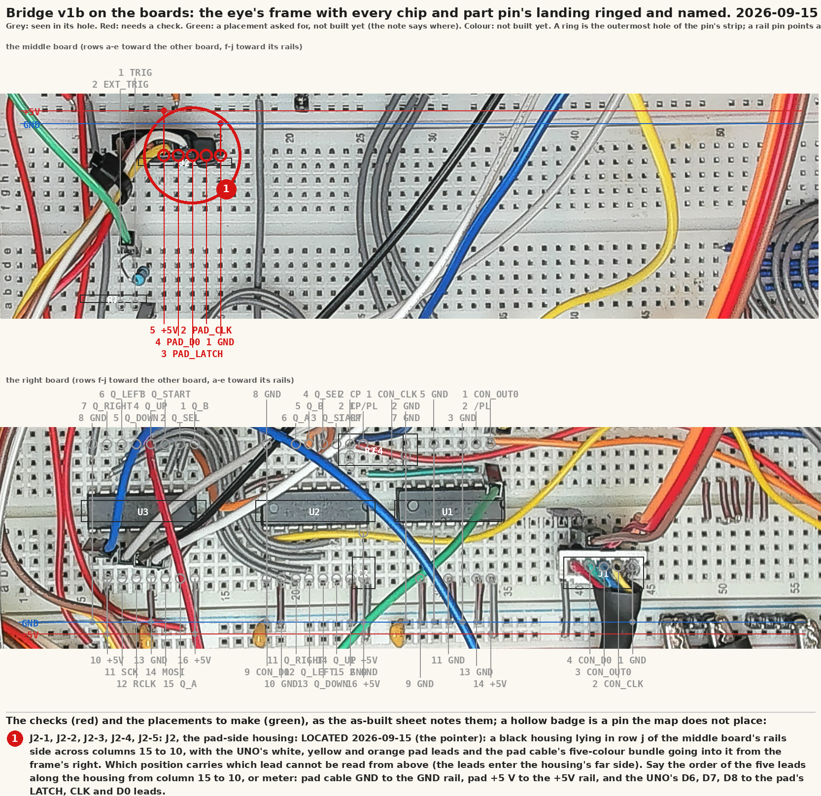
Read on 2026-09-11 from eighteen photographs of the bench, before any signal wire was placed. The purpose was to fix where every chip pin actually is, so the jumper list can name holes rather than pins, and to say where the cables and the ribbon should land so the wires stay short.
Everything with a number in it is derived. The hole for each pin
and every jumper are on the breadboard sheet (breadboard-v1b.svg),
which tools/breadboard.py draws from the schematic with this placement
written into it; the ribbon colours and the two breakouts are on the
cheat sheet (cheat-sheet.md). This page is the reading and the
reasoning, so a reader knows what was seen and what was inferred.
What the photographs settled
- Which block, which half. The chips sit in the right-hand block of the top breadboard, the one beside the rail pair that carries a black two-pin header. In that block rows a to e are on that rail's side and rows f to j on the middle rail pair. The row letters at the board's edge say so; the assumption the other way round was tried first and the letters refused it.
- Orientation. All three chips have their notch toward the higher column numbers, with the pin-1 dimple beside it on the f side. So pin 1 is in row f at each chip's highest column, the first half of the pins runs down the f side toward the lower columns, and the second half runs back along the e side. The breadboard tool has a hole rule for each notch direction and asserts both.
- Columns, counted from the printed 10, 20 and 30 marks with the pin shoulders as the guide, allowing for the camera's perspective: the inverter at 9 to 15, the 165 at 17 to 24, the 595 at 26 to 33, with 16 and 25 empty between them. Believed to within one column. Step 3.1 is what proves it: a wrong column puts the byte on the wrong pins and the scope pattern says so.
- Rails. On the right-edge pair the inner line is GND and the outer is +5 V; on the middle pair, GND is on the chip block's side. Both pairs are fed from the UNO's 5 V and GND, and bridged once at the low-column end. The console's own 5 V (the red lead) stays off the board.
- The ribbon from the UNO's digital header carries exactly the nine
pins the schematic uses: 2, 3, 5, 6, 7, 8, 10, 11 and 13, nothing on 4,
9 or 12. The colour of each is on the cheat sheet. Superseded
2026-09-15: the UNO's leads now run direct from its header
(
build-status-v1b.json, the second rig pose). - The eyes. The Pi's camera was on the bench but still pointed at
the windows; every frame it gave was the same three blinds. These
photographs came from a phone. The rig was locked on 2026-09-15
(
rig.md).
What to do with it
This was the plan on 2026-09-11; it was wired over the next four days
and the bridge read right through the console on 2026-09-15
(milestone-2026-09-15-rig-and-bridge.md).
Wire the supplies first (short stubs from each VCC and GND pin to the nearest rail, the spare inverter inputs to GND), then the console side, then the eight register-to-register wires, then the UNO side, as the breadboard sheet numbers them. Three of the eight register wires stay on the f side and run straight along a row; five have to cross the channel between U2's e-side inputs and U3's f-side outputs. Lay those five over the empty column between the two chips so they make one flat bundle rather than a fan across the packages.
One move shortens most of what is left: the nine-pin ribbon header is in the other block, so every one of its wires crosses the middle rails and arrives from the far side. Re-seated in the chip block, row a, directly across from the 595, the three SPI wires become three-hole stubs and the two console-side wires run along one row. The pad cable's header would sit the same way beside it. If the probes are to stay clipped where they are, move only the ribbon header.
Turning the 595 round would cut the channel crossings from five to three. It is already in the board with its legs formed, so it was left, and the count is recorded here rather than acted on.
Pulled at build time from nes-bench/docs/as-built-v1b.md; the repository is the one copy. The reports use some working words of their own: Words the reports use.