The build guide, in five sittings
Printable: NES controller-port bridge, v1b: drawing package TM-NESB-001 rev P (PDF); v1b as built, the checks called out on the photograph (PNG).
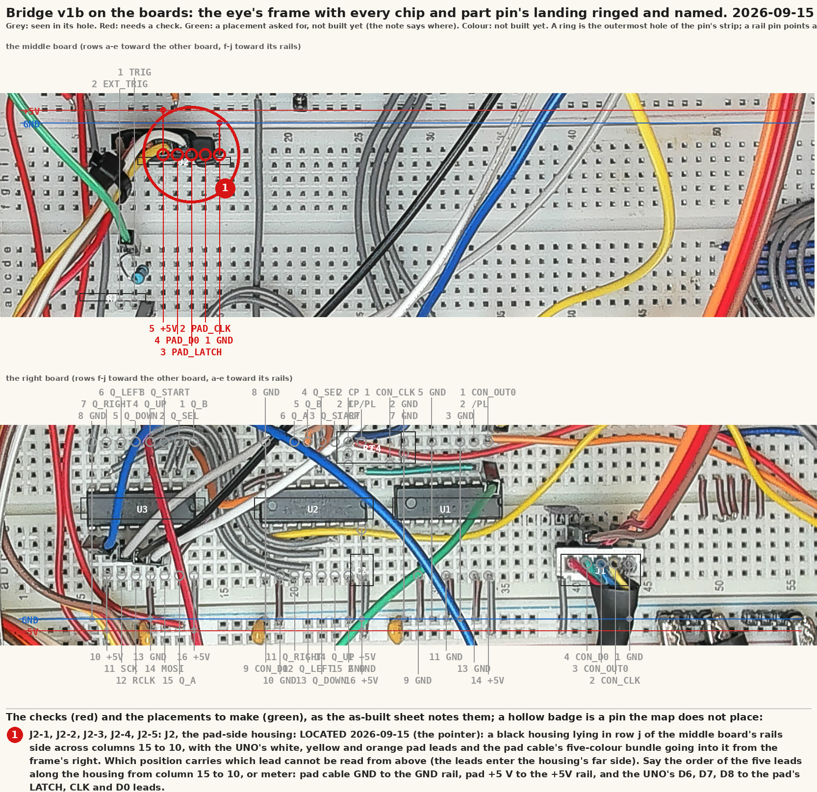
Generated by tools/build-guide.py from the step table in
tools/bringup.py and the log in docs/lab-log.jsonl. It is the
procedure that actually runs and the state it is actually in, so it
cannot drift from either. Re-run that tool and this updates.
One command per sitting. Each one prints what to do, waits, and then measures something. It never asks whether a step worked. A step that fails stops the run and tells you which one to repeat.
The running record, with every attempt and the photographs, is
the lab notebook. The working document for
whichever cycle is open, and the place the operator's own
observations are written down, is in docs/procedures/ in this
repository.
Where it stands
| sitting | what it is | state |
|---|---|---|
| 1 | Instruments | done |
| 2 | The console, measured | done |
| 3 | The bridge, built | not started |
| 4 | Joined | 1 of 2 steps |
| 5 | The head's hands | 1 of 3 steps |
Before the first sitting
Two things bite before anything else, and both are one line.
The serial port will refuse to open until your user is in the
dialout group:
sudo usermod -aG dialout $USER
Then log out and back in. A new shell is not enough. Check it took
with id -nG | grep dialout.
The scope's address lives in bench.local.md, which git ignores.
Nothing else needs it, and nothing else should carry it.
On the desk, over the five sittings: a meter, two scope probes, the UNO and a USB cable, the console open with a game in it, two original pads, the breadboard, a 74HCT04, a 74HC165, a 74HC595, three 100 nF capacitors, a 100 ohm resistor, a probe or a BNC lead to carry the bridge's trigger into the scope's CH1, the PC817 module, the relay module, and the Pi.
Sitting 1: Instruments
Nothing is wired. The scope answers, the UNO's port opens, the sketch is on it.
python3 tools/bringup.py --session 1
0.1 The scope answers, and says what it is (held)
- Power the scope and put it on the LAN.
- Its address belongs in bench.local.md, which git ignores. Nothing else needs it.
Then it asks the scope who it is over the LAN.
Last run 2026-09-08 12:41:12: held. DS1054Z, firmware 00.04.05.SP2
0.2 The workstation can open a serial port (held)
- Plug the Arduino UNO in, with nothing else connected to it yet: no chips, no console, no pad. This step only proves the port opens.
- It can be plugged into this workstation, or into the Raspberry Pi that is the head. For the Pi, run head/serial-bridge.py there and point the tools at it:
python3 tools/bringup.py --session 1 --bridge socket://<pi>:6545
Then it opens the UNO's serial port, and names the fix if it cannot.
Photographs:
docs/lab/00-uno-bare.jpg(wanted)
Last run 2026-09-08 12:41:14: held. socket://:6545 opens
0.3 The bridge firmware is on the UNO and answers STATUS (held)
- Flash the sketch, putting your own port after -p:
arduino-cli compile --fqbn arduino:avr:uno firmware/bridge-uno
arduino-cli upload  --fqbn arduino:avr:uno -p /dev/ttyACM0 firmware/bridge-uno
Then it sends STATUS and reads the bridge's reply.
Last run 2026-09-08 12:43:11: held. # mode pass latch 0 clocks 0 held 00
Sitting 2: The console, measured
Still nothing built. A meter and two probes on the console you already have.
python3 tools/bringup.py --session 2
1.1 The controller harness's colours against the port's pins (held)
Answers: wiring.md's port table is a published pinout until this step confirms it on THIS board.
- Console UNPLUGGED from the wall. Open it if it is not already.
- Two ways to attach a colour to a pin number, and the record keeps which you used. The port housing has its pin numbers moulded into the plastic beside the crimp terminals, four on one row and three on the other: photograph both rows and read them off. Or find the white header where the harness lands on the board and ring each pin out to the socket with the meter.
- The moulded numbers are the connector telling you its own numbering, which is worth more than a colour convention. What they do not tell you is whether the harness carries each pin to the board header unswapped. Only the meter does that, so 'both' is the strongest answer.
- Port pinout on THIS console, measured 2026-09-09 and written down in docs/wiring.md: 1 GND, 2 CLK, 3 OUT0, 4 D0, 5 +5V, and nothing carried on 6 or 7. The published table puts D3 on 5 and the supply on 7; it does not describe this board.
- Colours are not evidence on their own. Every pin gets a number from the connector or from the meter, never from what the colour usually means.
- If a breakout is spliced onto the harness, this step maps its leads too, because the breakout is what a probe actually lands on. Those leads are new wire in whatever colours were to hand and carry no convention at all.
- Two breakout leads the same colour is the case to watch: a probe's ground clip and its tip go on adjacent leads, and a clip on a driven line grounds it. This step refuses a shared colour that was only read off the housing, and asks you to ring those leads out from the board header first.
- MEASURED 2026-09-09, the hard way: ring a cable OUT OF CIRCUIT. A tone through a cable still plugged into the console goes through the console's own pull-ups and port buffers, and pins that share nothing beep anyway. The first pass on this bench came back with two pins on one lead, repeatably, and both readings were of the wrong circuit. Unplug the cable, then ring it.
Then it takes your continuity readings, and refuses fewer than four.
Photographs:
docs/lab/01-port-housing-pins-1-4.jpg(pushed)docs/lab/01-port-housing-pins-5-7.jpg(pushed)docs/lab/01-board-header.jpg(wanted)docs/lab/01-breakout-map-controller.jpg(pushed)docs/lab/01-breakout-ground-marked.jpg(pushed)
Last run 2026-09-08 13:26:56: held. 7 of 7 pins mapped, read off the pin numbers moulded into the port housing; the numbering is the housing's own, and step 1.2's +5V reading is what tests it
1.2 The port's idle levels with the console on (held)
- Console powered. Meter black on the lead step 1.1 rang out as GND.
- Measure the supply lead, then OUT0, then CLK, then D0.
- Do NOT go by the published pinout's numbers: step 1.1 is what says which lead is which on this board, and on this one the supply is not where the published table puts it.
- Expect: the supply near 5 V, OUT0 idling LOW, CLK idling HIGH, D0 pulled up.
- A scope on those leads answers this better than a meter does, and the step records which instrument you used.
Then it takes four meter readings and REFUSES to continue if the supply pin is not about 5 V.
Photographs:
docs/lab/01-meter-on-port.jpg(wanted)
Last run 2026-09-09 21:33:50: held. supply 5.0 V; OUT0 idles 0.091, CLK idles 5.002, D0 None, read with the scope CH4/CH1/CH2, 1x, grounds on the yellow lead; D0 not read
2.1 The scope on an original pad's port, a game running (held)
Answers: wiring.md's authored 'latch high a few us, clock low a few hundred ns, ~7 us between clocks, 60 polls/s'.
- Put an original pad in the console's OTHER port and start a game that polls.
- Scope CH1 probe on that port's pin 3 (OUT0, the latch).
- Scope CH2 probe on that port's pin 2 (CLK).
- Both probe grounds on port pin 1. Probes at 1x if they have a switch.
- This is the measurement that replaces four authored numbers at once.
Then it captures both lines and measures the latch pulse, the clock pulse, the gap between clocks and the polls per second.
Photographs:
docs/lab/02-probes-on-port.jpg(wanted)docs/lab/02-scope-screen.jpg(wanted)
Last run 2026-09-09 21:24:27: held. latch high 3.32 us, clock low 0.580 us, clock period 10.62 us, 60.10 polls/s, 8 clocks per latch over 15 latches
Sitting 3: The bridge, built
The breadboard, in two halves that are tested apart before they are joined.
python3 tools/bringup.py --session 3
3.1 U1 and U2 on the board, links on H..A, the pattern on QH
- Console OFF. Build only the console-facing half on the breadboard:
- The supply is the UNO's own 5 V pin, fed by its USB from the Pi, and NOT the console's pin 7. v1b is one 5 V domain (the schematic's first sheet says so), and the console shares only ground: its pin 1 to the UNO's GND. That is also the only 5 V available, because the breakout does not bring pin 7 out.
- Leads, from step 1.1's rung-out map: yellow GND, blue CLK, black OUT0, green D0, red +5V. Use the marks on the leads, not the port pin numbers, and not the published pinout.
- 74HCT04 (U1): pin 14 to the UNO's 5V, pin 7 to GND, pin 1 from the BLACK lead (OUT0).
- 74HC165 (U2): pin 16 to the UNO's 5V, pin 8 to GND, pin 15 (/CE) to GND, pin 10 (DS) to GND, pin 1 (/PL) from U1 pin 2, pin 2 (CP) from the BLUE lead (CLK), pin 9 (QH) to the GREEN lead (D0).
- The YELLOW lead is the ground the UNO shares with the console. Nothing goes on the RED lead: it is the console's own 5 V and this bridge runs from the UNO's.
- 100 nF across each chip's supply pins.
- Wire links on the eight inputs to make a KNOWN byte. In pad order A, B, Select, Start, Up, Down, Left, Right those are pins 6, 5, 4, 3, 14, 13, 12, 11, and LOW is pressed.
- Scope CH1 still on OUT0, CH2 moved to QH (U2 pin 9). Console on, game running.
Then it captures QH and decodes the eight bits against the byte your links make.
Photographs:
docs/lab/03-console-side-built.jpg(wanted)docs/lab/03-qh-on-scope.jpg(wanted)
4.1 The UNO drives the 595, measured on its outputs
- Console OFF and its port half left alone. On the UNO's side of the board:
- 74HC595 (U3): pin 16 to the UNO's 5V, pin 8 to GND, pin 13 (/OE) to GND, pin 10 (/SRCLR) to 5V, pin 14 (SER) from UNO D11, pin 11 (SRCLK) from UNO D13, pin 12 (RCLK) from UNO D10.
- 100 nF across its supply pins.
- Do NOT join U3's outputs to U2's inputs yet. Meter on QA (pin 15), black on GND.
Then it sets a byte, reads it back from STATUS, and has you meter two of the register's outputs.
Photographs:
docs/lab/04-uno-and-595.jpg(wanted)
4.2 The original pad polled by the bridge at 5 V
- This is the PAD HALF of the cut controller cable, the one that does NOT beep to the console's board header, with the pad on the end of it.
- Its leads carry the same colours as the plug half, because it is the same cable: yellow GND, blue CLK, black OUT0, green D0, red +5V.
- yellow to GND, RED to the UNO's 5V (the pad's supply comes from the bridge here, and red IS the supply lead on this cable), black (OUT0) to UNO D6, blue (CLK) to UNO D7, green (D0) to UNO D8.
- Console still off. The bridge drives this half; the console drives the other.
- You will be asked to hold buttons; the bridge's own poll should follow them.
Then it asks you to hold three buttons and checks each one reaches the bridge's pad byte.
Photographs:
docs/lab/04-pad-on-bridge.jpg(wanted)
Sitting 4: Joined
The halves wired together. B0's first gate.
python3 tools/bringup.py --session 4
5.1 The two halves joined, eight clocks per latch on a game (held)
Answers: the plan's B0 gate 1, which is the first thing the part gets to answer.
- Console OFF. Remove the wire links from U2's inputs and join the halves:
- U3 QA..QH (pins 15, 1, 2, 3, 4, 5, 6, 7) to U2 H..A (pins 6, 5, 4, 3, 14, 13, 12, 11).
- UNO D5 to port pin 3 (OUT0). UNO D2 to port pin 2 (CLK).
- The console's GND, the breadboard's GND and the UNO's GND are one net.
- Console on, a game running that polls the pad, MODE PASS.
- This is B0's first gate: eight clocks on every poll.
Then it listens to the bridge for twenty seconds and prints the clocks-per-poll histogram.
Photographs:
docs/lab/05-bridge-joined.jpg(wanted)docs/lab/05-console-running.jpg(wanted)
Last run 2026-09-15 17:52:14: held. 1202 polls in 20 s (60.1/s), clocks per poll {8: 1202} <- B0 gate 1 held
5.2 A pressed button reaches the console through the bridge
- Same setup. You will be asked to hold a button; the game should see it, and the bridge's log should carry the same byte at the same latches.
Then it checks the game reacts and the log carries the byte.
Photographs:
docs/lab/05-button-through.jpg(wanted)
Sitting 5: The head's hands
The trigger, the reset optocoupler and the power relay.
python3 tools/bringup.py --session 5
6.1 The trigger reaches the scope (held)
- UNO D3 through a 100 ohm resistor to the scope's CH1 (a probe, or a BNC lead): the DS1054Z has no external trigger input, MEASURED 2026-09-15, the source EXT is refused.
- CH1 is the master clock's channel later; until the mainboard is probed it is free, and afterwards TRIG and the clock take it by turns.
Then it arms the scope on CH1 and fires the bridge's trigger at a latch.
Photographs:
docs/lab/06-trigger-cable.jpg(wanted)
Last run 2026-09-15 21:14:18: held. TRIG 20 stopped the scope on CH1
6.2 The reset optocoupler pulses the console
- The breakout J3 is five ways straight through, colour for colour (1 brown, 2 red, 3 orange, 4 yellow, 5 white); 3 orange and 4 yellow are the reset button, orange 4.40 V above yellow with the console on (MEASURED 2026-09-17).
- PC817 module: OUT to 3 orange, its GND to 4 yellow, VCC unconnected, and the Pi's GPIO17 to INPUT + with INPUT - to the Pi's GND. The front panel's button stays wired in parallel.
Then it records which reset pad is ground and checks the pulse resets the console.
Photographs:
docs/lab/06-reset-pads.jpg(wanted)docs/lab/06-breakout-map-power-reset.jpg(pushed)
6.3 The power relay switches the console
- The relay's COM and NO across J3's 1 brown and 2 red, the front panel's power switch (metered 2026-09-17), in parallel with it. The front switch stays OFF for this step. MAINS SAFETY: nothing here is ever on the mains side.
- Relay module VCC to the Pi's 5V pin, IN to GPIO27 (high powers the console, MEASURED 2026-09-17), GND to the Pi's GND.
Then it refuses unless the contact is on the adapter side, then checks it switches.
Photographs:
docs/lab/06-relay-inline.jpg(wanted)
When a sitting is done
python3 tools/lab-notebook.py     # fold the run into the notebook
python3 tools/build-guide.py      # and update this page's state
Photographs go in docs/lab/ under exactly the name the tool asked
for. Push them and re-run those two: the notebook embeds the ones
that arrived and keeps naming the ones that have not, so nothing
here is ever a broken image and nothing is quietly forgotten.
Pulled at build time from nes-bench/docs/build-guide.md; the repository is the one copy. The reports use some working words of their own: Words the reports use.