The bench's parts list
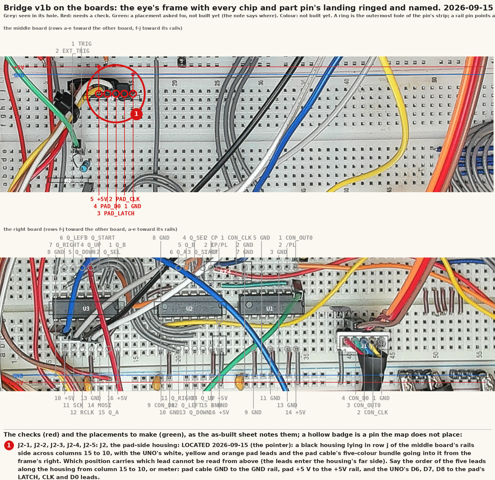
Printable: NES controller-port bridge, v1b: drawing package TM-NESB-001 rev P (PDF); v1b as built, the checks called out on the photograph (PNG); NES controller-port bridge, v2b: drawing package TM-NESB-002 rev A (PDF).
Generated by tools/parts.py from tools/draw-schematics.py, which is
the same file that draws the schematics. Nothing here is typed except
the status column: a drawing cannot know what is in a drawer.
The console, the Pi, the scope, the relay contacts and the port
connectors are drawn on the sheets with conn=True, which marks a
thing the bench CONNECTS TO rather than a part to buy, and this list
skips them for that reason. So everything below is something that has
to exist in a drawer before a sheet can be built.
What to gather
Every distinct part across every sheet, with where it is.
| part | status | note |
|---|---|---|
| 74HCT04 | on hand | SN74HCT04N, the tube that arrived 2026-09-09 |
| 74HC165 | on hand | the TI bag. v2b needs a second one |
| 100nF | on hand | v2b runs seven |
| 1k | on hand | R2, the clock pin's series element, placed 2026-09-15 |
| 100pF | on hand | C4, the clock pin's filter, placed 2026-09-15 |
| Arduino UNO R3 (ATmega328P) | on hand | the pile |
| 74HC595 | on hand | the box of 30 |
| 100R | on hand | the trigger |
| PC817 module | on hand | module, for the reset pads |
| relay module, 5 V coil | on hand | 5 V coil with an opto input |
| LM1881N | TO ORDER | the one real order. An old National part, mostly resellers now: buy two |
| 680k | check | LM1881 RSET. One resistor |
| 74HCT165 | on hand | the C6 sheets' register. HCT there because the C6 drives it at 3.3 V |
| 74LVC245 | on hand | C6 sheets only; no UNO sheet uses one any more |
| ESP32-C6-DevKitC-1 v1.2 | on hand | DevKitC-1 v1.2, the alternative build |
| 10k | on hand | pad adapter only; fitted on the P4 build 2026-09-27. The first part fitted there was 10 ohms: read the bands |
| TP4056 + protection | to order | pad adapter only |
| MCP1700-3302 LDO | to order | pad adapter only |
| slide | to order | pad adapter only, the power switch |
| power | to order | pad adapter only, the battery |
| +330R | check | pad adapter only, the LED |
| ESP32-WROOM-32 devkit | on hand | the 30-pin devkit on the breadboard, the BLE build since 2026-09-30 |
bench-v1b
Build this first. The UNO bridge, one port, everything at 5 V.
| ref | part | on the sheet |
|---|---|---|
| U1 | 74HCT04 at +5V | 2.0 V threshold: safe on NMOS OUT0 |
| U2 | 74HC165 at +5V (the TI bag) | H shifts out first |
| C1 | 100nF | +5V to GND |
| C2 | 100nF | +5V to GND |
| C3 | 100nF | +5V to GND |
| R2 | 1k | CON_CLK to CP |
| C4 | 100pF | CP to GND |
| A1 | Arduino UNO R3 (ATmega328P) | 5 V logic, 16 MHz |
| U3 | 74HC595 at +5V | one RCLK edge = one byte |
| R1 | 100R | TRIG to EXT_TRIG |
bench-v1b-head
v1b sheet 3: the head's hands, reset and power from the Pi (bring-up 6.2 and 6.3).
| ref | part | on the sheet |
|---|---|---|
| OK1 | PC817 module | open collector across the reset button |
| K1 | relay module, 5 V coil | MEASURED: GPIO27 high powers the console |
bench-v2b
Build this second. Two ports on one SPI chain, sync counted, still one UNO.
| ref | part | on the sheet |
|---|---|---|
| U1 | 74HCT04 at +5V | 4 spare inputs to GND |
| U2 | 74HC165 at +5V | H shifts out first |
| U6 | 74HC165 at +5V | H shifts out first |
| C1 | 100nF | +5V to GND |
| C2 | 100nF | +5V to GND |
| C3 | 100nF | +5V to GND |
| C4 | 100nF | +5V to GND |
| C5 | 100nF | +5V to GND |
| C6 | 100nF | +5V to GND |
| A1 | Arduino UNO R3 (ATmega328P) | serial 115200 to the Pi |
| U5 | 74HC595 at +5V | port 1's byte, shifted in second |
| U7 | 74HC595 at +5V | port 2's byte, chained from U5 |
| U8 | LM1881N at +5V | 5 V outputs: no 245 needed |
| C7 | 100nF | VIDEO to VID_AC |
| R2 | 680k | RSET to GND |
| C8 | 100nF | RSET to GND |
| R1 | 100R | TRIG to EXT_TRIG |
bench-v1
The ESP32-C6 alternative to v1b. Not the build.
| ref | part | on the sheet |
|---|---|---|
| U1 | 74HCT04 at +5V | 5 spare inputs to GND |
| U2 | 74HCT165 at +5V | H shifts out first |
| C1 | 100nF | +5V to GND |
| C2 | 100nF | +5V to GND |
| U3 | 74LVC245 at 3V3 | 5V tolerant inputs, A to B |
| C3 | 100nF | 3V3 to GND |
| U4 | ESP32-C6-DevKitC-1 v1.2 | RISC-V, BLE 5, Wi-Fi 6 |
| R1 | 100R | TRIG to EXT_TRIG |
| OK1 | PC817 module | open collector across reset |
| K1 | relay module, 5 V coil | opto in, active low |
bench-v2
The C6 alternative to v2b. Not the build.
| ref | part | on the sheet |
|---|---|---|
| U1 | 74HCT04 at +5V | 4 spare inputs to GND |
| U2 | 74HCT165 at +5V | H shifts out first |
| U6 | 74HCT165 at +5V | H shifts out first |
| U5 | 74HC595 at 3V3 | port 1 byte |
| U7 | 74HC595 at 3V3 | port 2 byte, chained |
| C1 | 100nF | +5V to GND |
| C2 | 100nF | +5V to GND |
| C3 | 100nF | 3V3 to GND |
| C4 | 100nF | 3V3 to GND |
| U8 | LM1881N at +5V | composite sync out |
| C6 | 100nF | VIDEO to VID_AC |
| R2 | 680k | RSET to GND |
| C7 | 100nF | RSET to GND |
| U3 | 74LVC245 at 3V3 | six lines down to 3V3 |
| U4 | ESP32-C6-DevKitC-1 v1.2 | RISC-V, BLE 5, Wi-Fi 6 |
| R1 | 100R | TRIG to EXT_TRIG |
pad-adapter
The original pad as a wireless HID device. A separate project.
| ref | part | on the sheet |
|---|---|---|
| R1 | 10k | PAD1_D0 to 3V3 |
| R2 | 10k | PAD2_D0 to 3V3 |
| U1 | ESP32-C6-DevKitC-1 v1.2 | NimBLE HID; no USB device |
| U2 | TP4056 + protection | LiPo charger module |
| U3 | MCP1700-3302 LDO | or the devkit's own 3V3 from VBUS |
| SW1 | slide | MODE_SW to GND |
| SW2 | power | VBAT to VBAT_SW |
| LED1 | +330R | LED to GND |
pad-ble
The C6 design, superseded. One pad, one pullup, the C6 on USB power; the board never accepted a flash, see pad-ble-p4.
| ref | part | on the sheet |
|---|---|---|
| R1 | 10k | PAD1_D0 to 3V3 |
| U1 | ESP32-C6-DevKitC-1 v1.2 | NimBLE HID keyboard; no USB device controller |
| C1 | 100nF | 3V3 to GND |
pad-ble-p4
The one to build. The same circuit on the board that actually flashes: a Waveshare ESP32-P4-Module-DEV-KIT, wired at header P6.
| ref | part | on the sheet |
|---|---|---|
| R1 | 10k | PAD1_D0 to 3V3 |
| C1 | 100nF | 3V3 to GND |
pad-ble-esp32
The BLE build, on the board with a radio of its own. The same circuit on a classic ESP32-WROOM-32 devkit, pins D25, D26 and D27; the C6 died and the P4 cannot do BLE.
| ref | part | on the sheet |
|---|---|---|
| R1 | 10k | PAD1_D0 to 3V3 |
| U1 | ESP32-WROOM-32 devkit | 30 pins; the labels are the board's own silkscreen; D is GPIO |
| C1 | 100nF | 3V3 to GND |
Pulled at build time from nes-bench/docs/parts.md; the repository is the one copy. The reports use some working words of their own: Words the reports use.